


Contact tracing via smartphone apps has been widely touted as an important way to control and limit the spread of the COVID-19 epidemic. However, basing contact-tracing on phone apps has several limitations. Here are instructions for constructing a contact tracing device prototype with a Raspberry Pi Zero-W. The constructed device is compatible with the Apple/Google Bluetooth contact tracing specification. It runs the Epidose software, which is based on the DP3T “unlinkable” design.
Materials
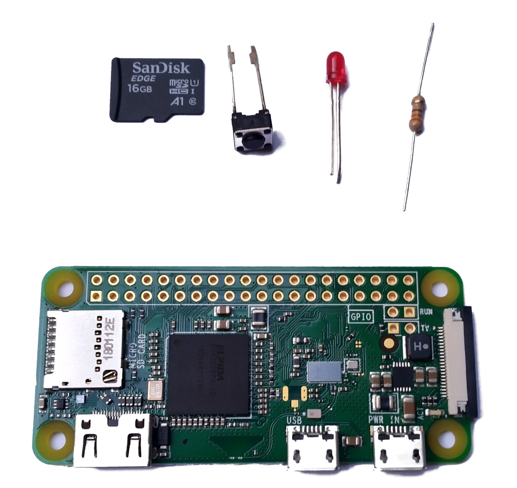
Figure 1: Required materials
Assemble the following materials:
- Raspberry Pi Zero-W
- MicroSD card (minimum recommended size 8 GB)
- Small (3mm) red LED
- 330 Ohm, 0.25 W resistor
- Single SPST momentary push button upload of their contacts to the Health Authority.
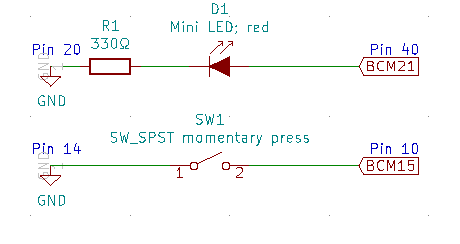
Figure 2: Circuit diagram
The objective of this construction is to provide the Raspberry Pi with a switch to authorize the contact upload and a LED to indicate that a user is at risk. The circuit diagram above shows this setup.
Connect the resistor to the LED
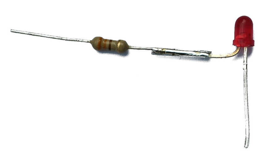
Figure 3: Resistor LED connection
Solder one end of the resistor (it doesn’t matter which) to the LED’s cathode (the shorter of the LED’s two wires) to obtain a 17mm long connection. The connected assembly should be able to fit in pins 20 and 40 of the Raspberry Pi.
Isolate the LED-resistor connection
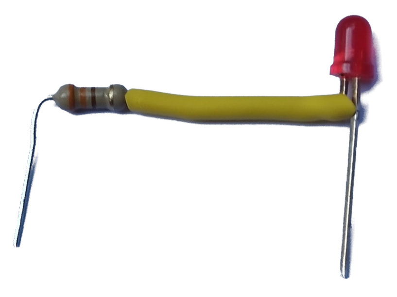
Figure 4: Isolating the connection
Cut a 17mm length from the smallest heat-shrink tube that can fit around the resistor, and slide it to cover the entire LED-resistor connection. Heat it to shrink.
Solder components on the Raspberry Pi
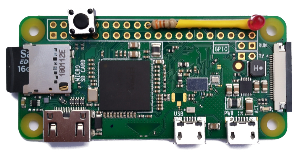
Figure 5: Assembled Raspberry Pi
- Solder the free end of the LED (its anode) to pin 40.
- Solder the free end of the resistor to pin 20.
- Solder the push button between pins 14 and 10 (orientation isn’t important).
Power up and install the Epidose software
- Connect the Raspberry Pi to a power source. A USB power bank can make this setup portable.
- Follow the instructions in the Epidose repository repository to install and configure the software.
- You can test the hardware’s operation by running the command
sudo venv/bin/python epidose/device/device_io.py --test. This allows you to toggle the LED by pressing the button. Press Control-C and then press the button to terminate the program.
—
Source of this article: https://www.spinellis.gr